HOME AUTOMATION PROJECT
Objective
• The primary objective of this project is to develop a home automation system with Android application controlled home appliances.
• This operation is achieved by any smart-phone or tablet with Android OS, upon a GUI based touch screen operation.
• This operation is achieved by any smart-phone or tablet with Android OS, upon a GUI based touch screen operation.
Project Discription
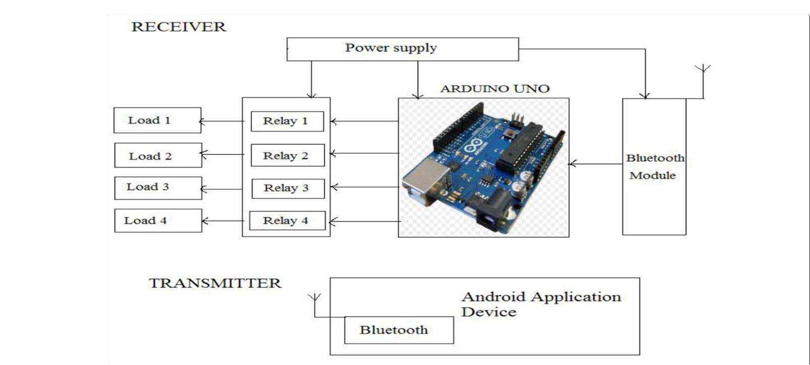
The aim of this project is to develop a home automation system with Android application controlled home appliances.
Thus this project consists of Arduino Uno board, Bluetooth module HC-05, 4 channel relay board, Two way switch and power supply. The number of channels depends on the number of appliances to control. Arduino Uno is powered with a 9V DC adaptor/power source. The relay module and Bluetooth module can be, in turn, powered using a board power supply of Arduino Uno.
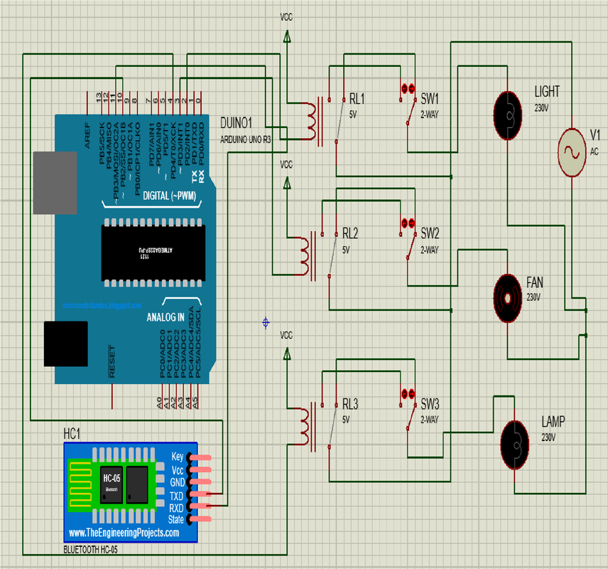
Circuit Diagram
Hardware Requirements
1. Arduino Uno Board
2. Bluetooth Module HC-05
3. Relay
4. Two Way Switch
5. Wires
2. Bluetooth Module HC-05
3. Relay
4. Two Way Switch
5. Wires
Software Requirements
1. Arduino Software (IDE)
2. Android Studio IDE
2. Android Studio IDE
Arduino Uno Board
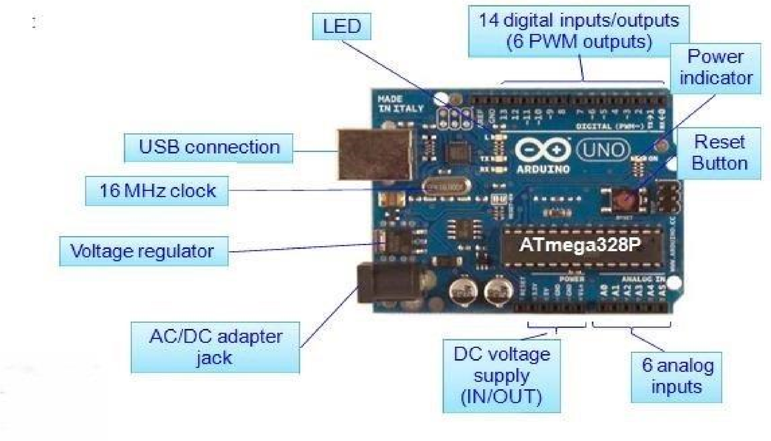
Arduino Uno is a microcontroller board based on the ATmega328P. It has 14 digital input/output pins (of which 6 can be used as PWM outputs), 6 analog inputs, a 16 MHz quartz crystal, a USB connection, a power jack, an ICSP header and a reset button. It contains everything needed to support the microcontroller; simply connect it to a computer with a USB cable or power it with a AC-to-DC adapter or battery to get started.
"Uno" means one in Italian and was chosen to mark the release of Arduino Software (IDE) 1.0. The Uno board and version 1.0 of Arduino Software (IDE) were the reference versions of Arduino, now evolved to newer releases. The Uno board is the first in a series of USB Arduino boards, and the reference model for the Arduino platform; for an extensive list of current, past or outdated boards see the Arduino index of boards.
"Uno" means one in Italian and was chosen to mark the release of Arduino Software (IDE) 1.0. The Uno board and version 1.0 of Arduino Software (IDE) were the reference versions of Arduino, now evolved to newer releases. The Uno board is the first in a series of USB Arduino boards, and the reference model for the Arduino platform; for an extensive list of current, past or outdated boards see the Arduino index of boards.
Bluetooth Module HC-05
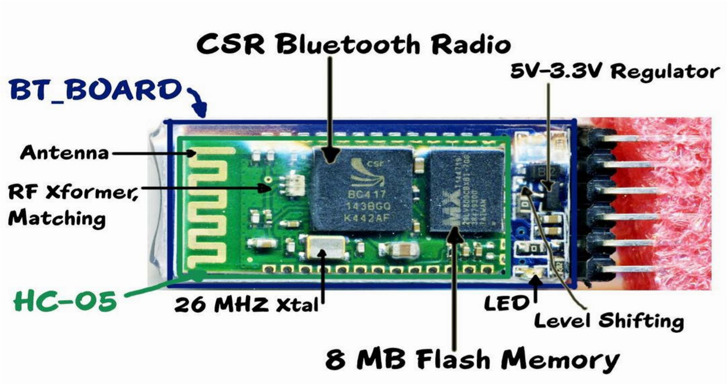
HC-05 module is an easy to use Bluetooth SPP (Serial Port Protocol) module, designed for transparent wireless serial connection setup.
Serial port Bluetooth module is fully qualified Bluetooth V2.0+EDR (Enhanced Data Rate) 3Mbps Modulation with complete 2.4GHz radio transceiver and baseband. It uses CSR Bluecore 04-External single chip Bluetooth system with CMOS technology and with AFH (Adaptive Frequency Hopping Feature). It has the footprint as small as 12.7mmx27mm.
Serial port Bluetooth module is fully qualified Bluetooth V2.0+EDR (Enhanced Data Rate) 3Mbps Modulation with complete 2.4GHz radio transceiver and baseband. It uses CSR Bluecore 04-External single chip Bluetooth system with CMOS technology and with AFH (Adaptive Frequency Hopping Feature). It has the footprint as small as 12.7mmx27mm.
|
|
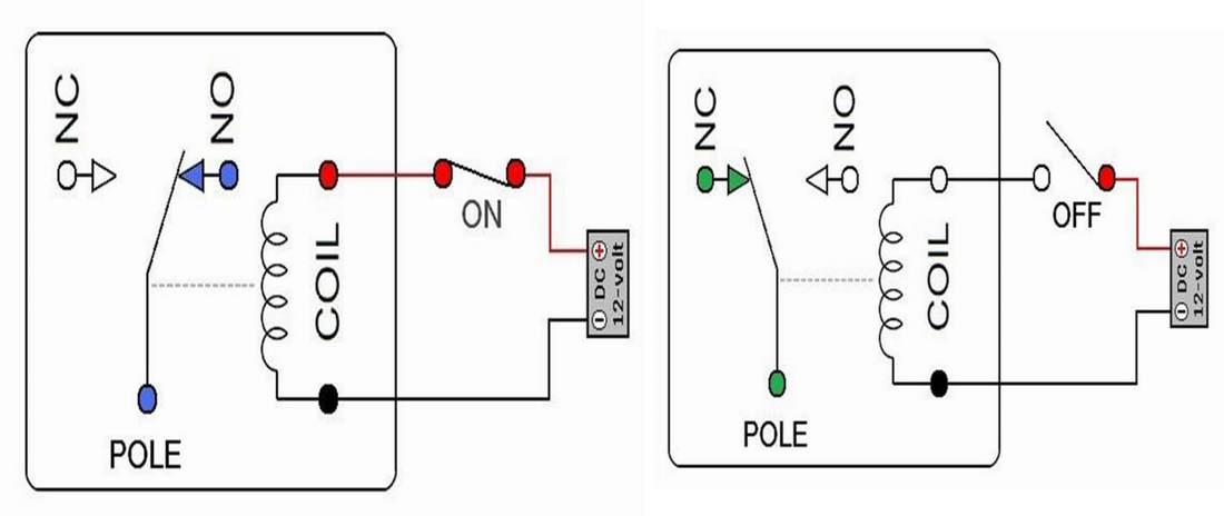
When power flows through the first circuit, it activates the electromagnet, generating a magnetic field that attracts a contact and activates the second circuit. When the power is switched off, a spring pulls the contact back up to its original position, switching the second circuit off again. This is an example of a "normally open" (NO) relay: the contacts in the second circuit are not connected by default, and switch on only when a current flows through the magnet. Other relays are "normally closed" (NC; the contacts are connected so a current flows through them by default) and switch off only when the magnet is activated, pulling or pushing the contacts apart. Normally open relays are the most common.
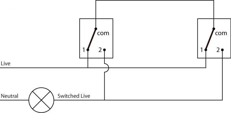
Two Way Switch
2 way switching means having two or more switches in different locations to control one lamp. They are wired so that operation of either switch will control the light. This arrangement is often found in stairways, with one switch upstairs and one switch downstairs or in long hallways with a switch at either end. Here we a have a schematic (Fig 2.3) which makes it easy to visualise how this circuit works. In this state the lamp is off, changing the position of either switch will switch the live to the lamp turning it on. If you now change the position of the other switch the circuit is broken once again.
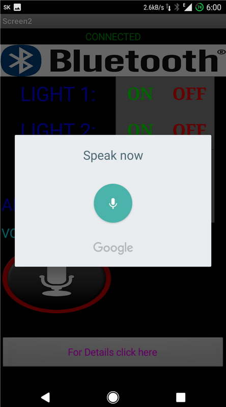
Android Application
This Anroid application is used to control the Electronic Appliances. The Screenshot of the Application is shown below,
|
|
Conclusion
The home automation system has been experimentally proven to work satisfactorily by connecting sample appliances to it and the appliances were successfully controlled from a wireless mobile device. The Bluetooth client was successfully tested on a multitude of different mobile phones from different manufacturers, thus proving its portability and wide compatibility. This project will not only provide convenience to the common man but will be a boon for the elderly and disabled.
Future Scope
This project can be further developed by integrating it with the internet to monitor your home while sitting in a remote area. By doing this, one can keep an eye on his or her home through an internet connected to the user’s mobile phone or PC or laptop. This will not only improve the security of your home in this modern day world but will also assist in conservation of energy like if you left any home appliance switched on by mistake, then you can check the status of the appliance on the graphical interface made on your mobile and can switch it off using the internet connectivity.
|
|
|
